The Atari Paddle Controller Atari Punk Console
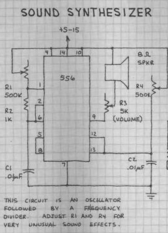
In 1982, Forrest Mims published a quadrille-paper book titled Engineer’s Notebook II: A Handbook of Integrated Circuit Applications. On page 101, he used Signetics’ 556 Dual Timer IC to create a Sound Synthesizer. He later renamed it the “Stepped-Tone Generator,” but it is now popularly known as the Atari Punk Console (APC).

Atari Punk Console theory of operation
Mims’ explanation was that
This circuit is an oscillator followed by a frequency divider. Adjust R1 and R4 for very unusual sound effects.
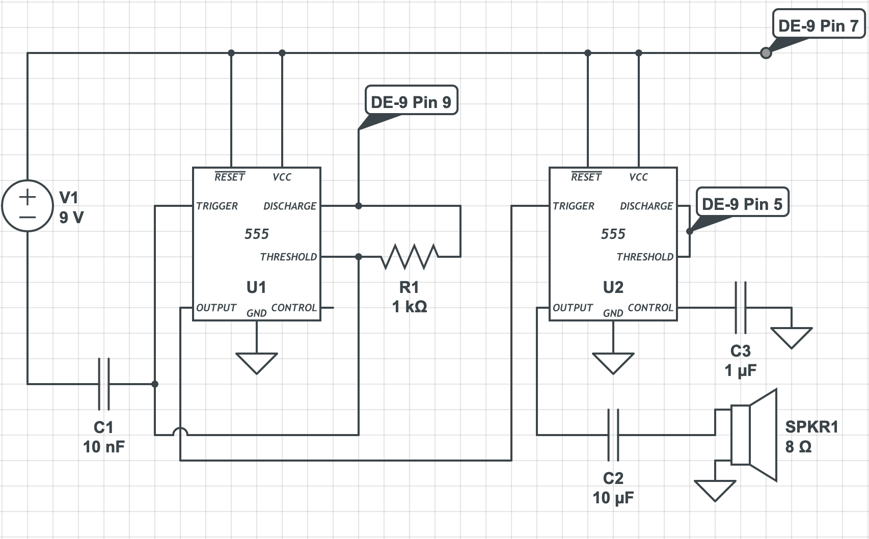
Another way to explain this is that the first timer is an astable multivibrator, generating square waves, and the second timer is a monostable multivibrator (“one-shot”) used to control the pulse width of each oscillation from the first timer.
Two 500KΩ potentiometers are used to control the frequency and pulse width. Coincidentally, there is an actual Atari product that includes two potentiometers—the Atari paddle controller—though they are 1MΩ, which will cause them to behave slightly differently.
Introducing the Atari Paddle Controller Atari Punk Console


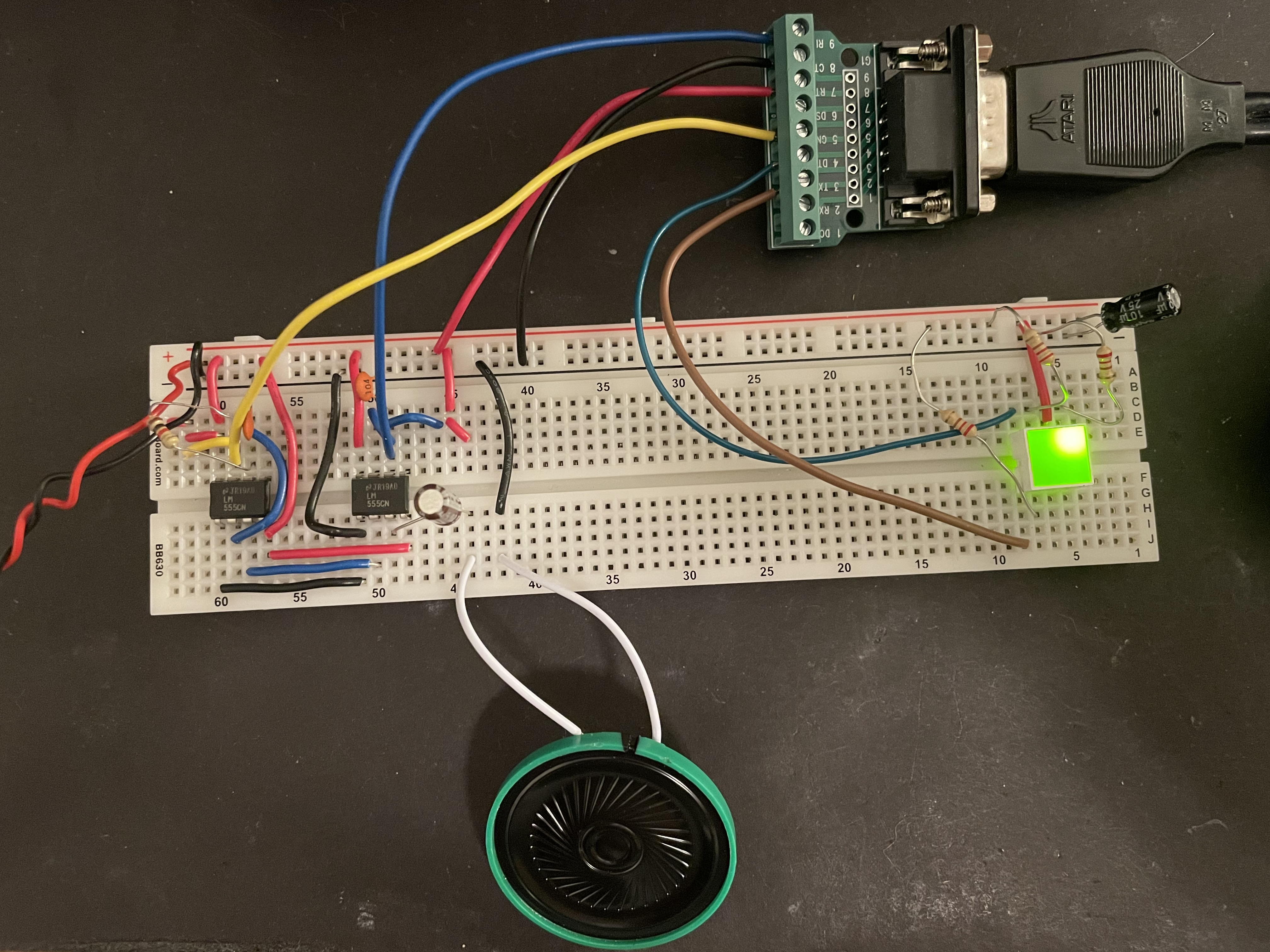
By tying pin 7 to Vcc, pin 8 to ground, and pins 5 and 9 to the discharge pins of the timers, the APCAPC is ready to bring you sonic joy. Forrest Mims says “5-15V” for Vcc, so you can power this with pretty much whatever shady battery, USB cable, or voltage regulator you have handy.
The right side of the breadboard has an HLMP-2855 LED light bar, which contains 4 LEDs in a grid arrangement. I tied one LED to the power rails (with a current limiting resistor, of course), and two of them to the paddles’ button pins (3 and 4) to put on a little flashlight rave. The buttons are tied to ground, so connect them to the cathode, and use a current limiting resistor to connect the anodes to Vcc.
I like the symmetry of starting this post with a grid of engineering paper, and ending with a grid of LEDs.