PS/2 keyboard on a 65C02 breadboard computer
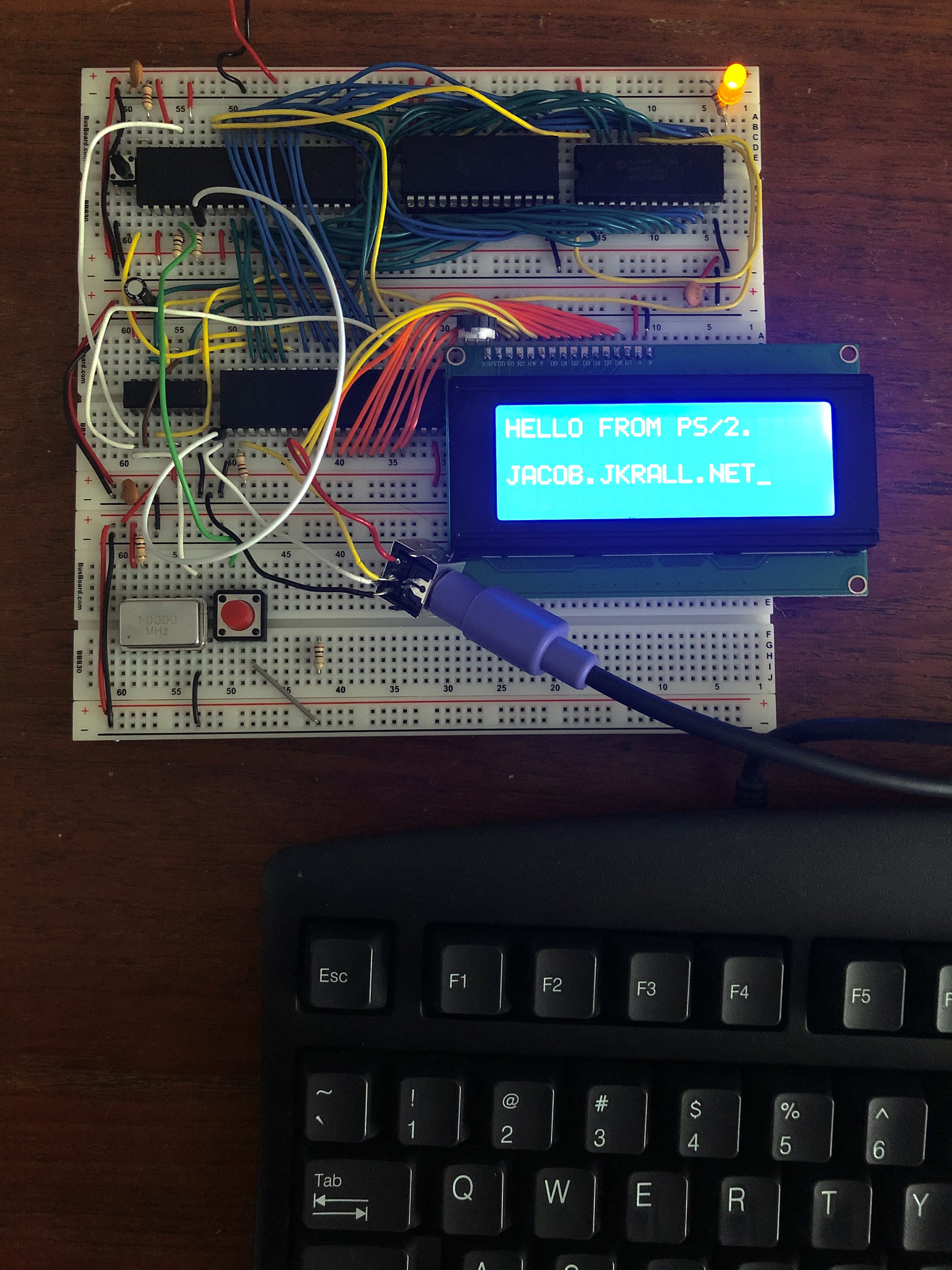
I’ve been following Ben Eater’s series on building a 6502 computer on a breadboard. Once I got the 65C22 VIA working with a bigger 4-line x 20-character LCD display, I wondered if I could interface the computer directly with an external keyboard. The IBM Personal System/2 (PS/2), released in 1987, had what became a very commonly used keyboard and mouse connector, which uses some convenient electrical signals for interfacing with even-more-ancient technology like the WDC 65C02 and 65C22 this breadboard computer is based on.
Physical layout
Electrically, PS/2 is very simple: power, ground, clock, and data. The clock is driven by a microcontroller inside the keyboard, at a rate around 10-16.7 kHz. The data line is valid when the clock is low. Data and clock are open-collectors, so they can be connected directly to the computer with pullup resistors.
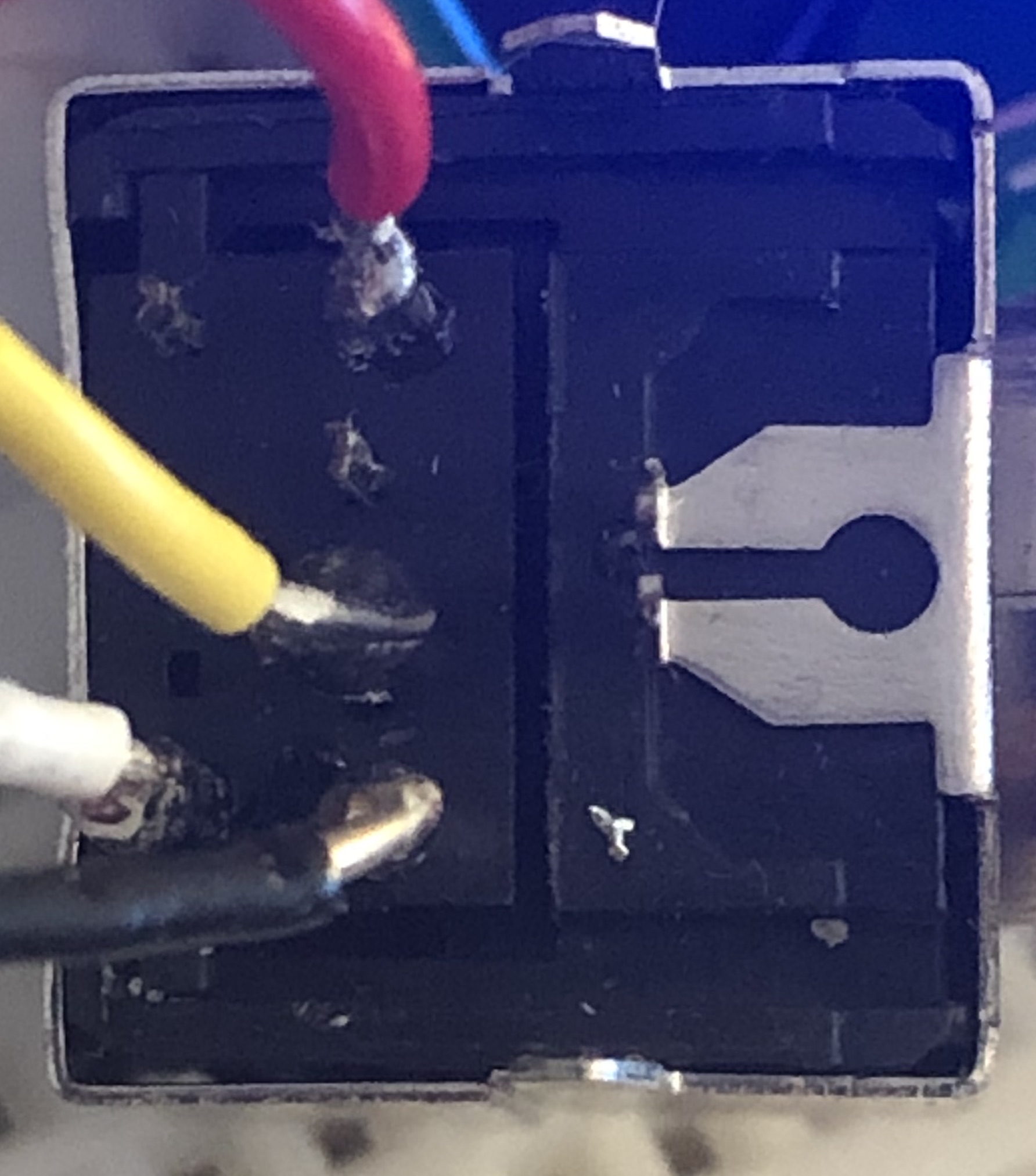
I acquired a PS/2 connector and soldered four wires to the correct pins. +5V on power, 0V on ground, and the keyboard flashed its three status lights so I know I didn’t short it out or install the pins backwards. That’s good.
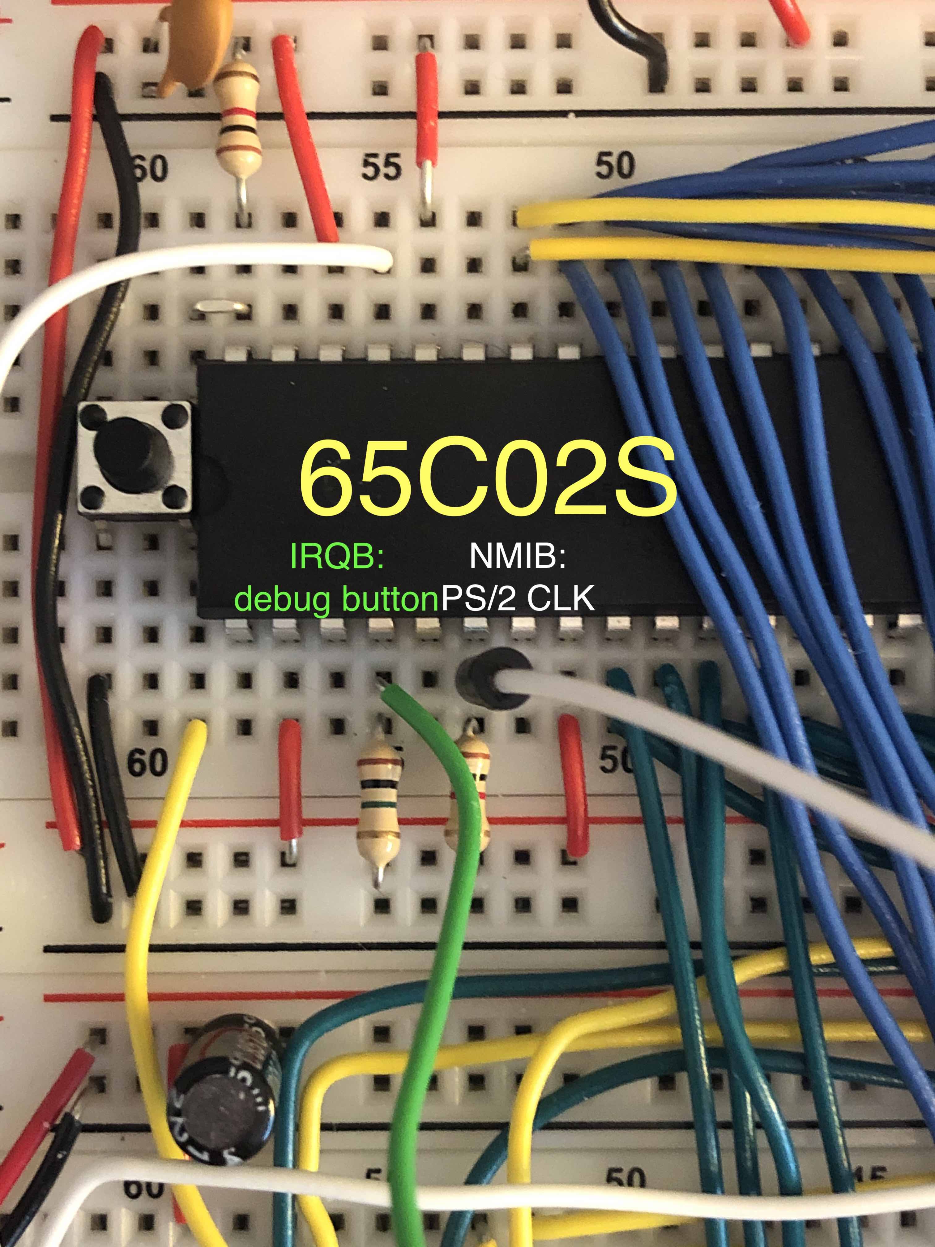
I connected the PS/2 clock wire to NMIB (pin 6 on the DIP-40 W65C02S),
and tied it to the 5V rail using a 1kΩ pull-up resistor.
Because I was making hardware changes anyway, I also added a pushbutton
to IRQB (pin 4 of the W65C02S) for an easy way to trigger a second
kind of interrupt. (It helped a lot when debugging - in the interrupt
service handler, I could print whatever info I wanted.)
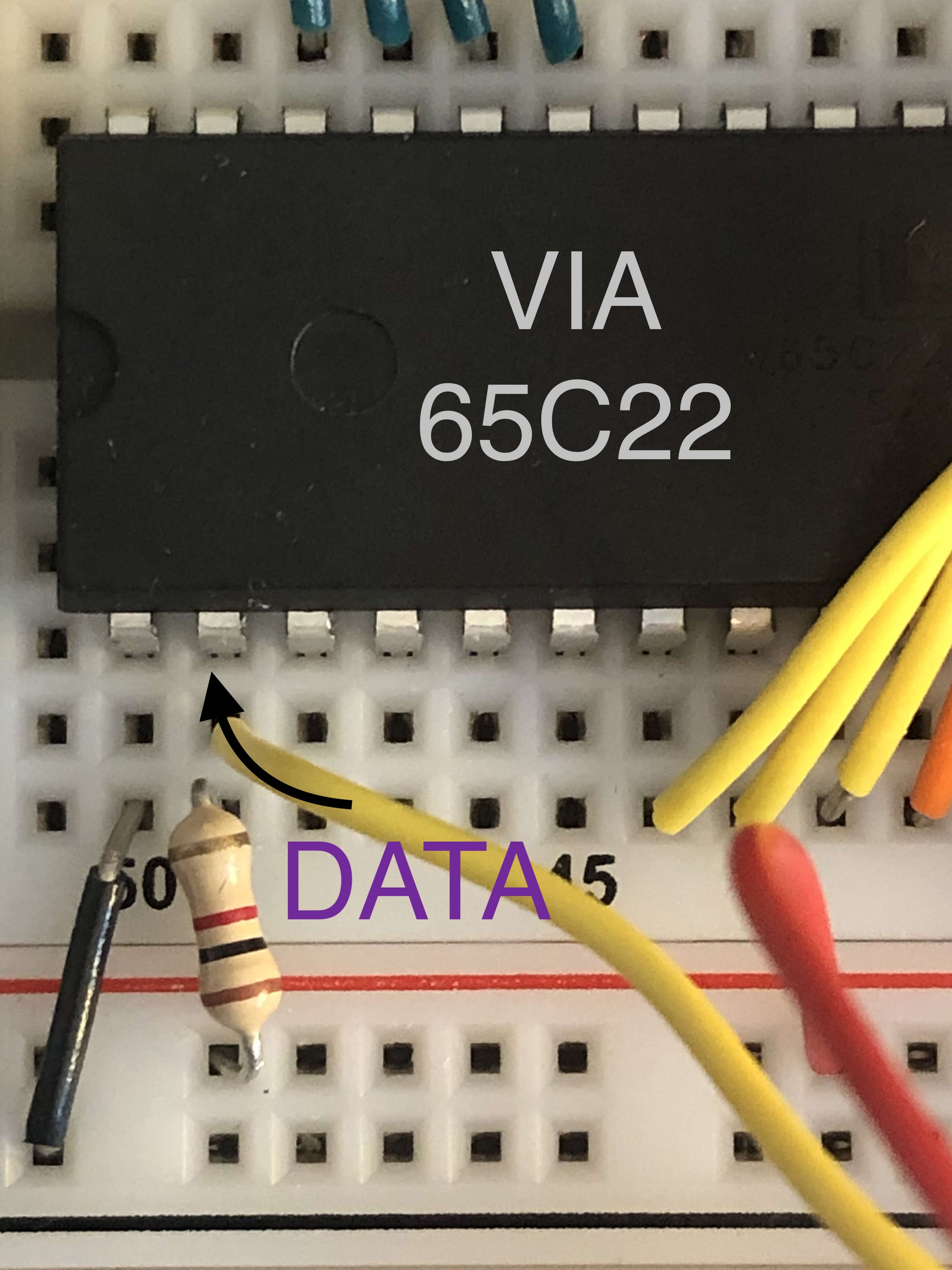
Similarly, the data line is tied to PA0 (pin 2 of the 40-pin W65C22)
with a 1kΩ pull-up resistor as well.
6502 interrupts
The two interrupt pins on the 6502 are used slightly differently.
The non-maskable interrupt (NMIB) is edge-triggered, which generally
means only one interrupt source can use it. But that’s great for PS/2,
since we only want to interrupt on each clock signal once.
The interrupt request (IRQB) is level-triggered: the processor will
generate interrupts as long as interrupts are enabled and the input is low.
This means it’s much easier to service multiple devices, but there has to
be some way to clear the interrupt on the other end - and we don’t really have
that ability on the PS/2 bus, so it’s not a good choice, unless we want
to add some glue logic. That sounds expensive, and I don’t have a lot of
space left on my breadboard.
Using some nicer vasm flags
The WDC65C02S supports some additional opcodes, so I’m going to let vasm
understand those with the -wdc02 flag. I also added -chklabels, -wfail,
and -x. These warn when a label matches a mnemonic/directive, return an
error code on warnings, and show an error when referencing an undefined
symbol, respectively.
Do-nothing interrupts
First, define two no-op interrupt handlers, nmi and irq_brk.
irq_brk:
  rti

nmi:
  rti
Set up the vectors for each of them - this replaces the .org $fffc
from Ben Eater’s video:
  .org $fffa
  .word nmi
  .word reset
  .word irq_brk
In our reset handler, we will need to enable interrupts with
cliNow, it’s time to declare and initialize some memory. First, name four bytes in the zero-page:
KEY_BUF_X = $00
KEY_READ_X = $01
PS2_BIT_NUMBER = $02
PS2_NEXT_BYTE = $03
The actual values aren’t important - they’re pointers to bytes in the first 256B of RAM.
The first two, KEY_BUF_X and KEY_READ_X are offsets into a
256-byte circular array. Let’s name that array:
KEY_BUF = $0200The second two variables are used for decoding the PS/2 byte. For now,
let’s initialize them all to zero in the reset handler.
  stz KEY_BUF_X
  stz KEY_READ_X
  stz PS2_BIT_NUMBER
  stz PS2_NEXT_BYTE
All of this does nothing, but we’ve reserved all the space in RAM needed to decode the raw PS/2 byte stream.
Handling the interrupts
As I mentioned before, the PS/2 clock rate is between 10-16.7 kHz, and the data line is only valid for the low half of the clock cycle.
My computer has a 1MHz clock, so that means we have 1M/16.7k = 59.88 cycles to completely handle the NMI. And the data is only valid in the first half.
The WDC65C02 takes 6 (or 7?) cycles to process an interrupt, and can only process an interrupt once the previous instruction has completed, so we may already be 12 or 13 cycles in by the time we start the very first instruction of the interrupt handler!
We’ll read PORTA from the 65C22 VIA, and need to use some bitmasking to get
the first bit. It would be very convenient if the high bit were set, instead
of the low bit, but I’m already using PA7 for the E pin on the LCD, and
don’t want to break compatibility with Ben’s code just for convenience.
So, during the interrupt routine, I’ll rotate PA0 into the PA7 position,
and then mask it out.
Define the PA7 bit mask:
KEY_DATA = %10000000And update the NMI handler to write the PS/2 bit into KEY_BUF:
nmi:
  pha ; preserve A register

  lda PORTA ; the data bit is in the low bit of A
  ror       ; the data bit is in the carry flag
  ror       ; the data bit is in the high bit of A
  and #KEY_DATA ; all other bits have been cleared


  ; store A in KEY_BUF[KEY_BUF_X]
  phx
  ldx KEY_BUF_X
  sta KEY_BUF,x
  inc KEY_BUF_X

  ; restore X,A in correct order
  plx
  pla

  ; complete the interrupt
  rti
Decoding the bitstream
Decoding a PS/2 bitstream takes a few more cycles than we can afford in our non-maskable interrupt handler. So, the handler is wasteful and writes the bit samples as bytes in a 256-byte circular buffer.
In our main loop, we can chase after the bitstream using a simple state machine.
The states are defined by the number of bits we’ve seen.
First bit (state 0) is a start bit. It’s followed by eight data bits (states 1-8), least-significant-first. Then, there’s a parity bit (state 9). Then, there’s a stop bit (state 10).
loop:

ps2_check_bit:
  lda KEY_READ_X
  cmp KEY_BUF_X
  beq loop

process_one_ps2_bit:
  lda PS2_BIT_NUMBER
  cmp #0
  beq ps2_start_bit
  cmp #9
  beq ps2_parity_bit
  cmp #10
  beq ps2_stop_bit
  ; otherwise, fallthrough to ps2_data_bit

ps2_data_bit:
  ; move the $80/$00 into the top bit of PS2_NEXT_BYTE
  ldx KEY_READ_X
  lda PS2_NEXT_BYTE
  ror
  and #$7F
  ora KEY_BUF,x
  sta PS2_NEXT_BYTE

next_ps2_bit:
  ; advance the state machine
  inc PS2_BIT_NUMBER
  ; advance the read-bit pointer
  inc KEY_READ_X
  ; check if there are more bits to decode
  jmp ps2_check_bit

ps2_start_bit:
  ; TODO: we could verify the start bit is correct
  jmp next_ps2_bit
ps2_parity_bit:
  ; TODO: we could verify the parity bit is correct
  jmp next_ps2_bit

ps2_stop_bit:
  lda PS2_NEXT_BYTE
  ; TODO: we could verify the stop bit is correct
  ; TODO: we have successfully decoded the PS/2 byte
  ;       into the A register.
  stz PS2_BIT_NUMBER
  inc KEY_READ_X
  ; give the main loop (currently empty) a chance to run
  jmp loop
Reading scan codes
PS/2 does not send ASCII, it sends scan codes. Most PS/2 keyboards use the “Set 2” codes. The characters we are concerned with send a one-byte “make” code when the key is pressed (and a few times per second while the key is held), and a two-byte “break” code when the key is released.
A nice abstraction would be to decode these scancodes into a buffer, which would allow us to do line editing and so forth, but I’m just going to print all the characters I recognize directly to the LCD.
In ps2_stop_bit, add a
jsr print_ps2_keyand let’s go implement that now.
First, we need to create a map for the PS/2 scan codes. You can sort of see how the key matrix is wired in the keyboard.
  .align 8
ps2_scan_codes:
  ;       0123456789ABCDEF
  .asc "??????????????`?" ; 0
  .asc "?????Q1???ZSAW2?" ; 1
  .asc "?CXDE43?? VFTR5?" ; 2
  .asc "?NBHGY6???MJU78?" ; 3
  .asc "?,KIO09??./L;P-?" ; 4
  .asc "??'?[=?????]?\??" ; 5
Now, add another byte to the zero page so we can ignore break codes:
  PS2_IGNORE_NEXT_CODE = $04

  ; ... in `reset`:
  stz PS2_IGNORE_NEXT_CODE
Finally, let’s implement the print_ps2_key subroutine:
print_ps2_key:
  ; if we received #$F0 previously, ignore this byte
  bit PS2_IGNORE_NEXT_CODE
  bmi code_ignored

  ; A is scan code.
  ; see if we got a break code
  cmp #$F0
  beq ignore_next

  ; Bounds check ps2_scan_codes
  cmp #$5F
  bpl too_high

  ; index into ps2_scan_codes
  tax
  lda ps2_scan_codes,x
  jsr print_char
  rts

too_high:
  rts

ignore_next:
  lda #$FF
  sta PS2_IGNORE_NEXT_CODE
  rts

code_ignored:
  stz PS2_IGNORE_NEXT_CODE
  rts
There’s still a ton more work to do, like Shift, Backspace, arrow keys and even outputting lines to the correct place on the screen. Like I mentioned above, it would probably make more sense to store these ASCII codes in a line buffer, or whatever suits your application’s purpose. You could even use another circular buffer with chasing pointers.
But hey, at least we can say HELLO, WORLD, and that’s what matters.
Postscript (1 day later)
Fairly frequently, I saw extraneous NMIs. Since I’m not doing any
error checking on the stop/start/parity bits, this would appear as a
shifted bit in the byte stream. The first thing I changed was using
a 1kΩ resistor on the NMI pin instead of 1MΩ. I thought
the higher resistance was causing the voltage to rise too slowly.
It certainly helped, but I still could rarely type a full 80-character
page of text without seeing a desynchronization. I tried using a
faster 1.8432 MHz oscillator, to see if my interrupt code was too slow,
but that neither made sense, nor fixed the issue. (A 7.3728 MHz
oscillator was too fast for the existing LCD code. Needs NOPs.)
Finally, I wondered if the additional power demanded by the keyboard
(and its long cable) was still causing voltage drops.
I added another 10µF capacitor to the power rails,
near the PS/2 power wires, and now it is much better.
I still see desynchronization if I mash on the keyboard, but it’s
waaaaay more usable than it was.